 CCNA Badging
Introduction
During the course of my studies for the ICDN 2 exam, these are the notes that I took. These notes are based around the CBT Nuggets videos as that is the training material I choose to use. All labs in these notes were completed using a combination of Cisco Packet Tracer and GNS3. You can use any variety of physical equipment as well as a virtual option like GNS3 and Packet Tracer.
I am by no means an expert, these are just what I created to make my way through the exam. Your mileage may very depending on use case. Good luck with your studies!
Cisco CCNA ICND2 200-105
Welcome to ICND2
- Course Overview
- Cisco’s Mission
- Move you to the Wide Are network
- PPP
- PPPoE
- Content You’ll Cover
- Routing
- OSPF
- EIGRP
- BGP
- HSRP
- SNMP
- IP SLA
- Routing
- Cisco’s Mission
- Supplementary Files
- GNS3
- Getting the most from this series
- Repetition, Repetition, Repetition
- Take Notes; Write Down Key Information you hear
- Build a lab or GNs3/VIRL Away
- Study Hard
- Dig Deeper
- “Fall” In Love
Review Lab
Rebuilding ICND 1
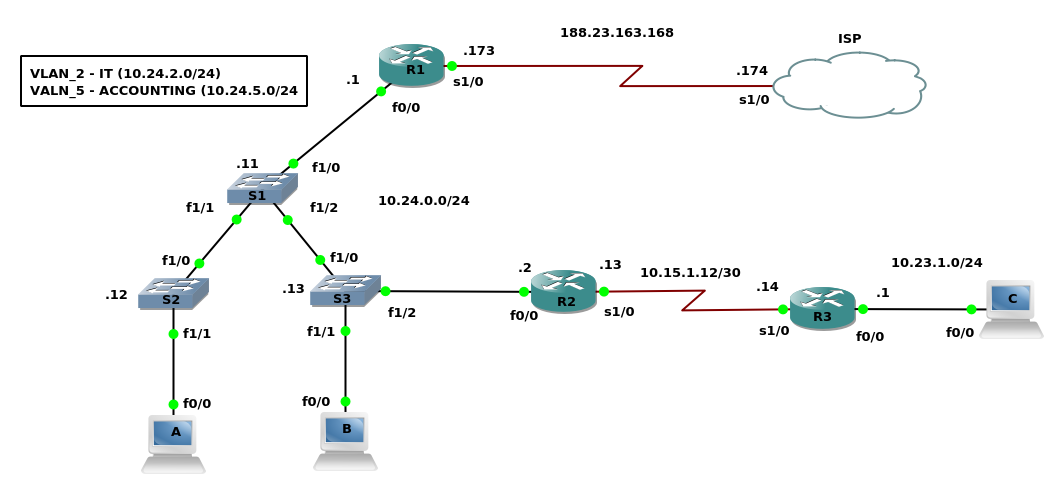
- Understanding the Rebuilding Lab
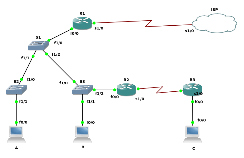
- Building the Topology in GNS3
- Drop 4 Routers
- Configuration
- ISP symbol = Cloud
- ISP, R1, R2, R3 Slot 1 = NM-4t
- Configuration
- Drop 3 Routers
- Configuration
- S1, S2, S3 Slot 1 NM-16ESW
- Change Symbol to ethernet-switch
- Configuration
- Drop 3 Routers
- Configuration
- A, B, C
- Change Symbol to Computer
- Configuration
- Route Cables Per the Scenario Parameters
- Drop 4 Routers
- Building the Topology in GNS3
- Base Config
- Deploying the Base Configuration
- Make your edits, and copy and past into the proper device.
- IP Addressing, Speed, and Duplex
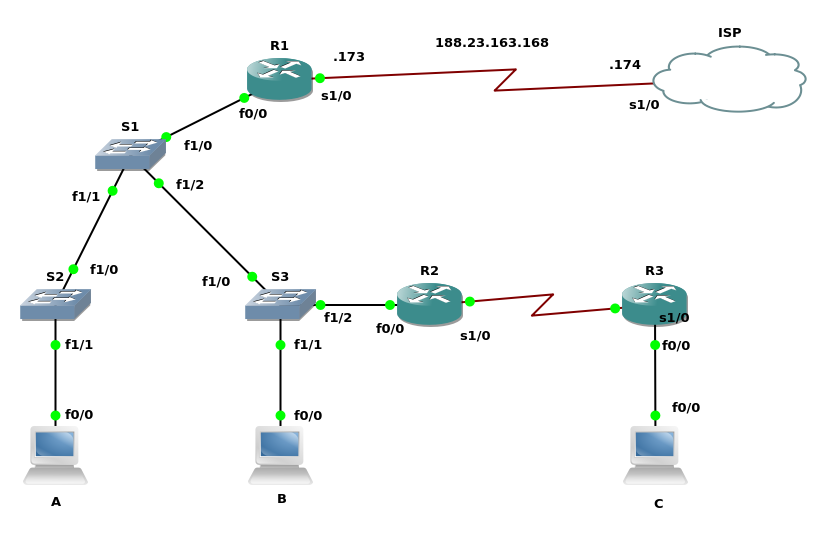
- Configure Router and Switches IP Addresses
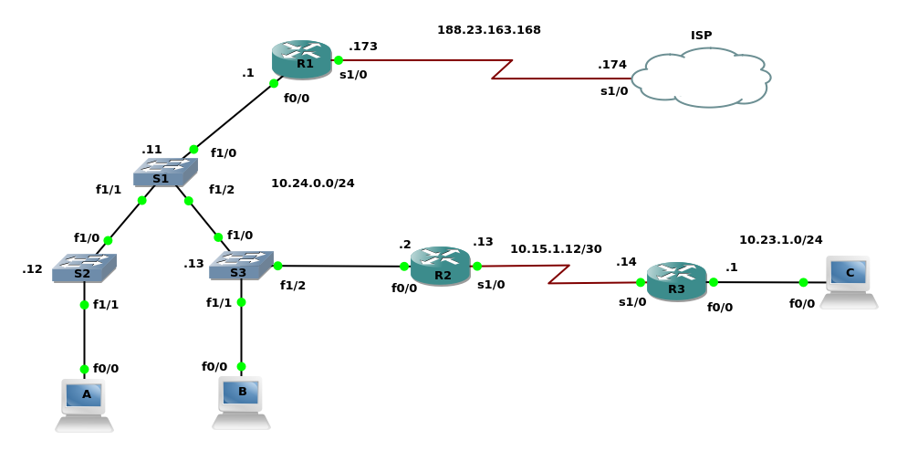
- Configure Router and Switches IP Addresses
- Enabling RIPv2 Routing
- Configure RIPv2 through the Network Environment
- Static Routes, Default Routes
- Trunking, VTP, and VLANs
- Configure interwitch trunk links and user VLANs.
- VLAN database: This has been deprecated, however is the only way to add VLANs in GNS3
- FLASH Disk needs to be added to the switches for them to work properly
- Right Click
- Configure
- Select the group
- Memories and disks
- PCMCIA Size :4Mb
- PCMCIA Size :4Mb
- Memories and disks
- Right Click
- Configure interwitch trunk links and user VLANs.
- Router on a stick and DHCP services
- Configure Router on a Stick and Router DHCP Services
- sh ip dhcp binding
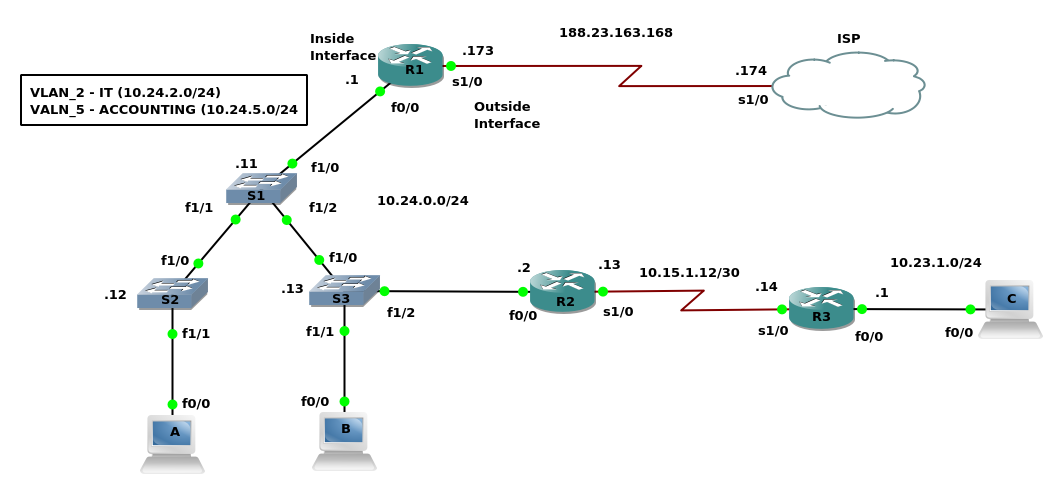
- Network Address Translation
- Configure Network Address Translation
- Add More memory to Router 1
- right click
- configure
- memory and disk
- RAM = 256
- Add More memory to Router 1
- Configure Network Address Translation
- Standard Access Lists
- Configure a Standard Access list for security
- Copy and past those commands to the other switches, and test telnet using Router 1 Serial 1 / 0 interface.
telnet 10.24.0.2 /source-interface serial 1/0
Rebuilding ICND 1 Conclusion
- At this point the top level overview review from ICND 1 has been completed. From this point forward all material discussed will be directly related to ICND 2. All review configs can be found here.
Spanning Tree Protocol
What Does STP Do
- STP Technology Overview
- Fact: Redundancy is Good!
- Single Switch Connections mean single point of failure
- Simple to create redundant links
- Spanning tree loop
-
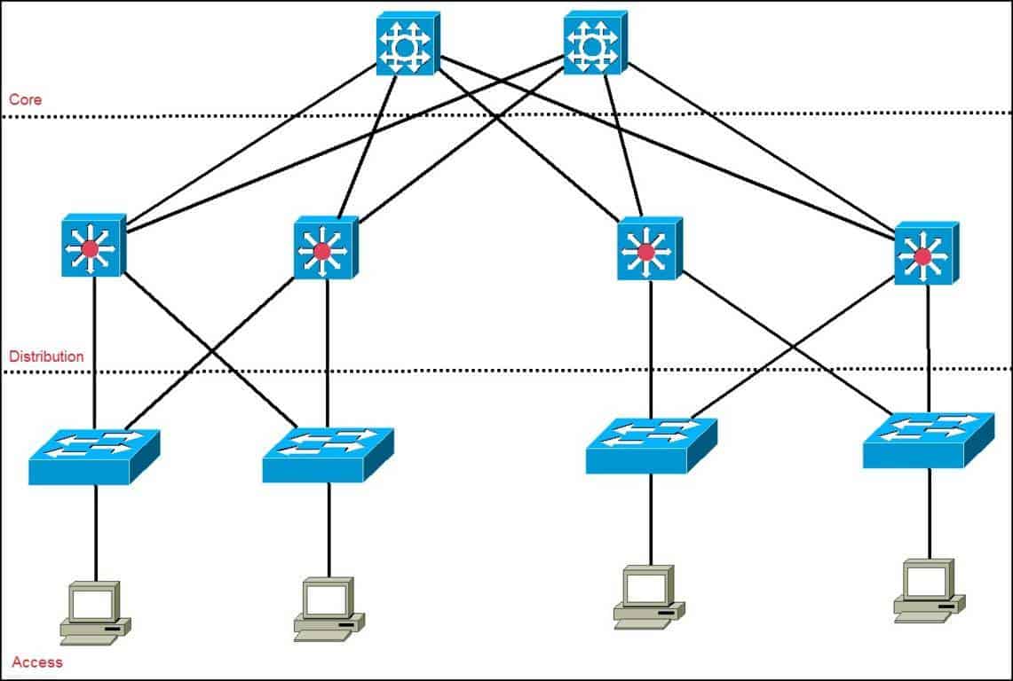
Cisco Hierarchical Model
- Layered Approach allows for easy, manageable growth
- Etherchannel can provide more bandwidth on key links
- Redundant connections eliminate a single point of failure
- Fact: Redundancy is Good!
- What is the Root Bridge?
- How does STP find the best way around?
- Elect the Root
- Find the best path to the root
-
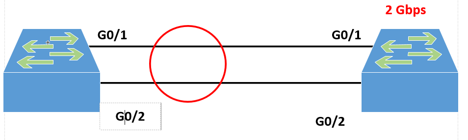
Lowest Cost
Link Bandwidth Cost 10Mbps 100 100 Mbps 19 1Gbps 4 10Gbps 1 -
Lowest bridge id
- Priority Number
-
Lowest Port Number
-
- Block whatever is left over
Understanding the Standards
- Common Spanning Tree (CST or STP - 802.1d)
- Created in 1993
- takes 30-50 seconds to remove the block, and rebuild the connectivity
- time based
- Per-VLAN Spanning Tree (PVST)
- Cisco Proprietary
- Rapid Spanning Tree (RSTP - 802.1w)
- Takes 2 seconds to remove the block
- activity based
- Will inter operate with Common Spanning tree.
- Per-VLAN Rapid Spanning Tree (PVRST)
- Cisco Proprietary
- Multiple Spanning Tree Protocol (MSTP - 802.1s)
- Took the Cisco Proprietary and improved upon it as an industry standard.
How the Root Bridge is Elected
- The most important switch…EVA!
- Two Elements:
- Bridge Priority
- 0-65535
- 32768 is default
- Bridge MAC
- Switches own MAC address
- Bridge Priority
- …Combined into one:
- Bridge ID
- Made of the Priority and MAC address combined
- The lower the bridge ID, the better the chance of it becoming Root Bridge
- Sample Bridge IDs:
- 32768.00A0.1101.B011
- 32768.00A0.FF01.6689
- 32768.0010.FF32.991B
- Sample Bridge IDs:
- Bridge ID
- Two Elements:
- Terminology: Bridge Priority, MAC, ID, BPDU
show spanning-tree- Root ID
- Bridge ID
- shows sys-id-ext which adds up to the number of VLANs you have
- Root Bridge in the Cisco Three-Tier hierarchy should be on the Distribution Layer, where one switch is set to Primary, and the other as secondary/backup
- Primary Switch 4096
- Backup Switch 8192
- Access Layer stays at Default
spanning-tree vlan 1 priority 4096
- Following the BPDU Process
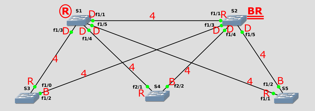
Will the Real Network Topology Step Forward
- How to determine your network topology
- Lower left switch is our root bridge
- All switches have a cost of 4
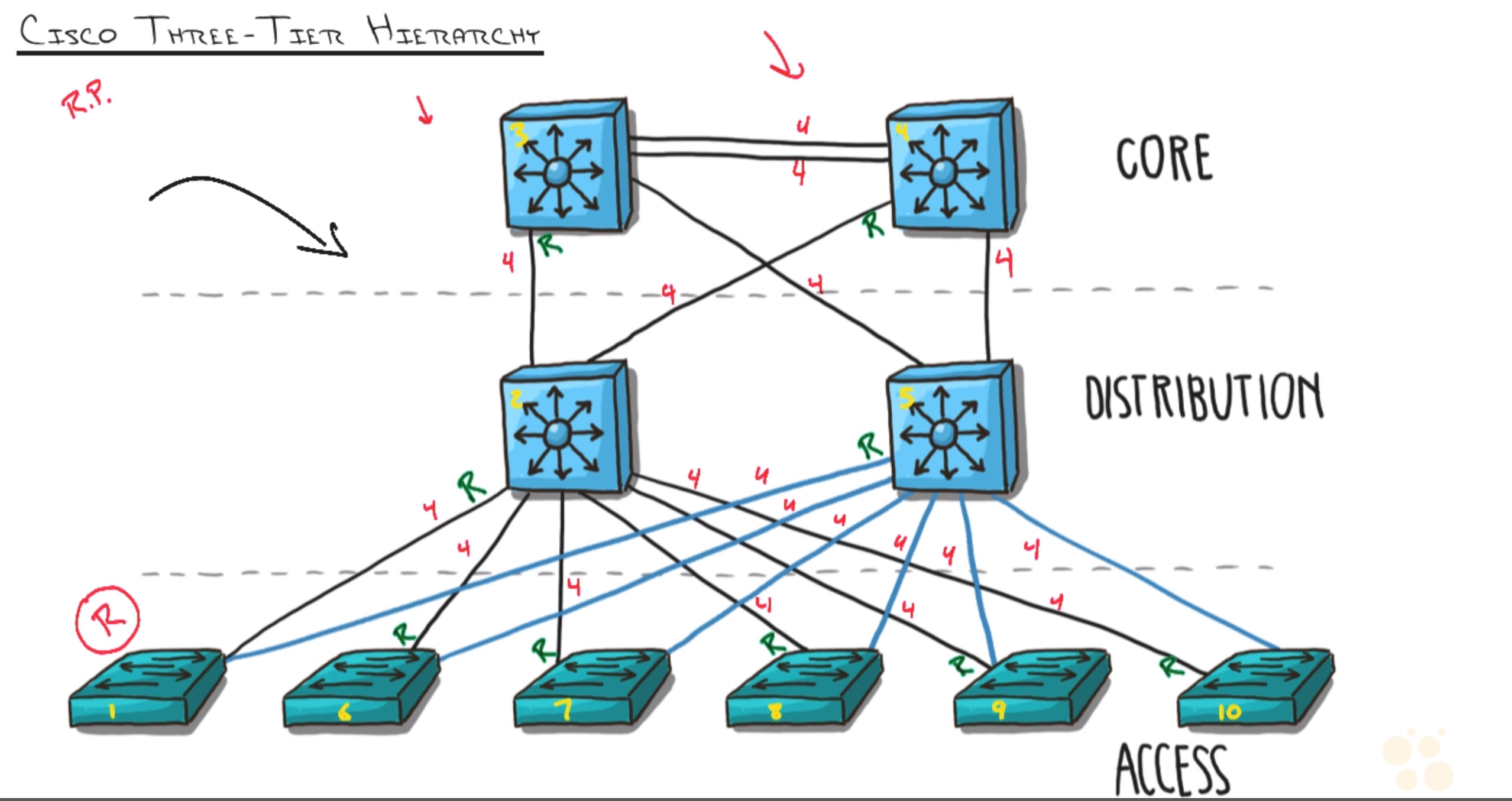
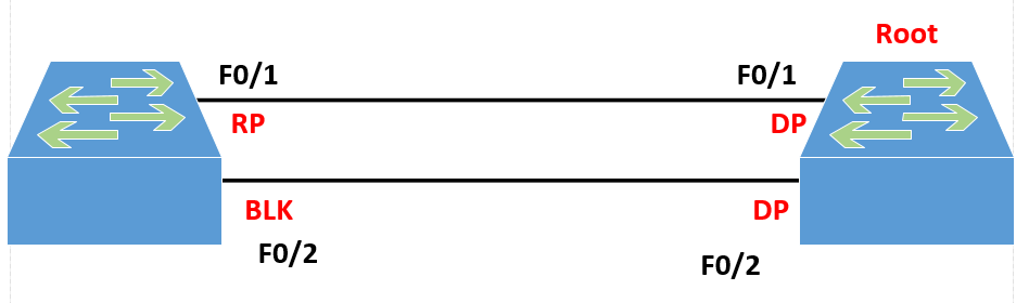
- 1 Designated Port, there can never be 2 Designated Port
- 1 side is the Root Port, the other side is Designated port
- Only one side of the connection gets blocked thus disabling the link
- All switches have a cost of 4
- Lower left switch is our root bridge
Lab - Build, Configure, Test
- Connecting the topology and discovering the root bridge in a random network
- Questions
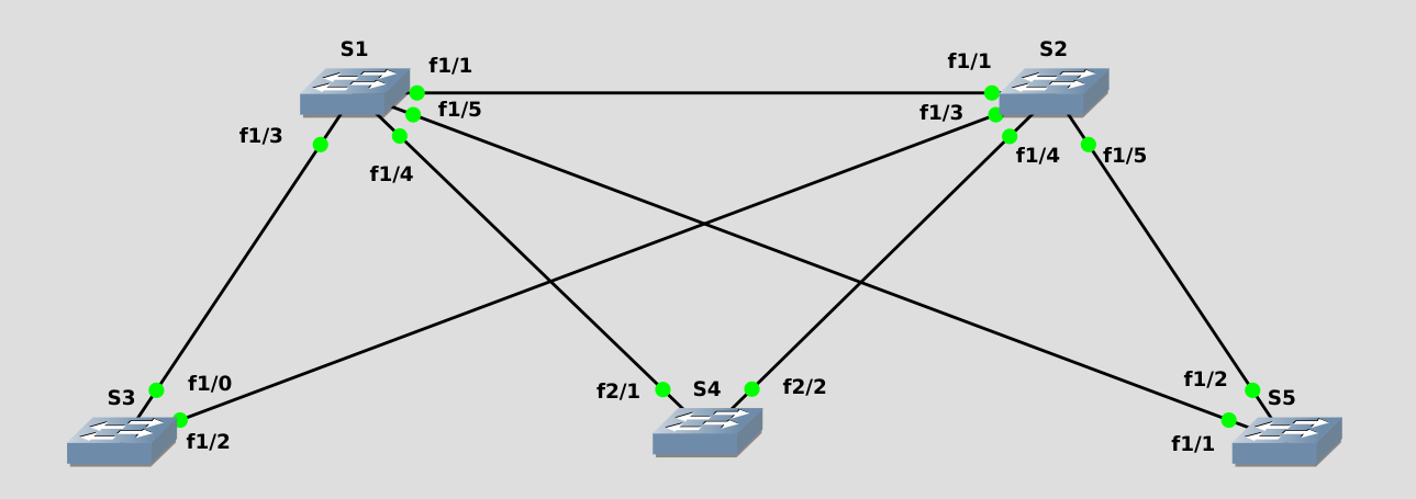
- Ensure switches have a basic base configuration and connect as shown
- Use the proper show commands to determine the version of
STP running,port status, andidentifytheRoot Bridge- STP Version
- ieee
- 802.1d
- Port Status
- Altn - blocks connection out of switch
- Desg - allows traffic to forward through the switch
- Root - Port which the device uses to send traffic to the root bridge, not necessary connected to the root bridge
- Root Bridge
- SW5 is the root bridge
- STP Version
- Cause a Root Port outage; determine how long it takes to converge
- 30 Seconds
- STP - Listen (15 Seconds)
- listening for BPDU
- STP - Learn (15 Seconds)
- learning mac addresses so it could learn what the network looked like
- STP - Listen (15 Seconds)
- 30 Seconds
- Change all switches to use RSTP test the outage again
- 2 Seconds
- Unlike Spanning tree which is passive, Rapid Spanning-tree is active, so it doesn’t wait for the Listening and Learning Timers to expire
- 2 Seconds
- Modify the bridge priority to elect SW1 as the Root Bridge, SW2 as the Backup Root: diagram port results and verify your assumptions are correct on the switch
- Intentionally selecting the root bridge
- Verifying what you should know to be true
Portfast and BPDUGuard
Configuring the STP " Option Features"
- Configure Portfast on all non-trunking ports of Dr. Evil
- Ensure Dr. Evil is indeed the STP root Bridge of the Network
- Protect Dr. Evil from other managed devices by correctly configuring BPDUGuard
- Ensure BPDUGuard is working correctly - connect Mini-Me to the network and ensure appropriate action is taken
Switch Services
Stacking and Chassis Aggregation
- What is a Switch Stack?
- Understanding the Benefits of Stacking
- Cisco’s Stackwise
- Links the Switches Together, Physically and Logically
- Administer Multiple Switches as one
- Similar to a Chassis-Based Switch
- Cisco’s Stackwise
- Stacking: a Visual Inspection
Security at Layer 2
- Locking Down Switchports: 802.1x
- The Security Mindset: Inside vs. Outside
- 802.1x focuses on the inside of the network by adding authentication to you network.
- EAP - the
Extendable Authentication Protocol - Rely on other things
- Domain Membership
- User Accounts
- Relies on server authentication
- EAP - the
- 802.1x focuses on the inside of the network by adding authentication to you network.
- The Goal of 802.1X
- The Concepts behind it: EAP, Radius/TACAS
- The Security Mindset: Inside vs. Outside
- DHCP Snooping
- Rouge DHCP: Simple Mistake or evil intent
- The Antidote: DHCP Snooping
- Managing Trust and Untrust
- Non-Default VLANs
- Every Cisco switch does VLANs out of the box
- Most organizations begin with VLAN 1
- Cisco Best Practice: No vlan 1 Anywhere, Especially on Trunk Connections
Etherchannel
Etherchannel is Awesome
- Bundling Instead of Blocking
- How would STP handle the following situation
- SPT would do the following
- SPT would block the ports on the unused link to ensure no loop was created.
- SPT would do the following
- Common EtherChange Options
- This Bundling takes Place at the
ASIClevel and allows for up to 8 connections to be bundled- Allows for 8 cables to be connected
- Works best in groups of 2, 4, 8, not none binary numbers
- Allows for Load Balancing via:
- Mac Address
- IP Address
- TCP and UDP port number
- A Collapsed Core would be a valid use case for 8 cables
- Initially designed for directly connected switches only.
- LAG - Link Aggregation Group
- This can be used for servers, as well as many other devices not support this capability.
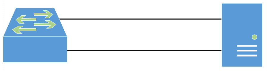
- This can be used for servers, as well as many other devices not support this capability.
- This Bundling takes Place at the
- There are two options for how to create Etherchannels
- First Option is using a negotiation protocol
- PAGP
- Cisco Proprietary
- Modes: On, Desirable, Auto
- Cisco Recommend configuring one switch as Desirable, and the other as Auto
- LACP
- Industry Standard
- Modes: On, Active, Passive
- Configure on as Active and the other as Passive
- PAGP
- Hard Coding
- Not recommended
- Could cause a spanning tree loop if not configured correctly.
- On - This indicates that the mode has been hardcoded
- First Option is using a negotiation protocol
- How would STP handle the following situation
- Configuration Steps
- Base interfaces must have identical configuration (Speed, Duplex, Mode, VLANs)
- Use the Channel-group command to create the etherchannel
- All Configuration done on the Virtual Port-Channel IInterface after bundling
- Best Verification: show etherchannel summary
Lab - Configuring Etherchannel Bundles of Joy
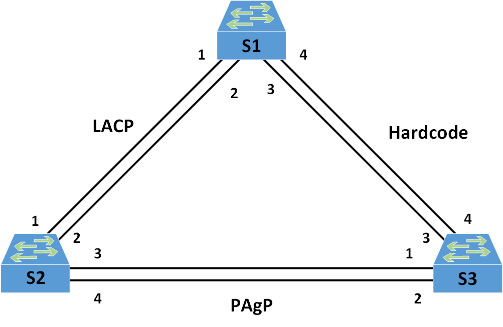
- Configuring Etherchannel
- Beginning with a base configuration, set all ports as access ports in VLAN 1
- Configure Etherchannel on the interfaces between S2 and S3 using PAgP
- Configure Etherchannel on the interfaces between S1 and S2 using LACP
- Configure hardcoded Etherchannel on the interfaces between S1 and S3
- Examine the configuration using show commands to verify Etherchannel works correctly
- Misconfigure an interface in the PAgP/LACP bundle. What Happens?
- Fix the issue. What happens now?
- Verifying It’s working correctly
IOS Software
Fully Understanding the IOS Boot Process
- Why alternate IOS locations can be good
- Check the configuration Register
- 2100: ROMMON
- confreg
- tftpdnld/set
- xmodem
- 2101: RXBOOT
- 2102: Boot Normally
- 2142: Ignore NVRAM
- 2100: ROMMON
- Check for “Boot System” Commands in the Startup config
- Checks startup config for boot system commands
- can access a TFTP server
- Stored in NVRAM
- Look for the first IOS Image in flash
- Broadcast for a TFTP server
- Check the configuration Register
- The Function of the configuration Register
- boot into RXBOOT and ROMMON
- Change forgotten password
- How to change IOS Boot Behavior
sh version
conf t
  config-register 0x2100

sh flash
conf t
  boot system flash://ios-version desired
  boot system tftp://ios-version desired X.X.X.X
Upgrading the IOS
- Getting a New Version of the IOS
- Setting up a TFTP Server
- Performing the Backup of the old IOS/Install of a new IOS
-
Access the device shown in the picture
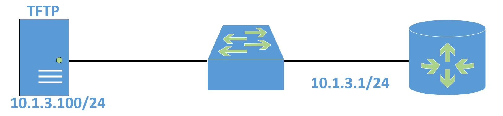
-
Backup the IOS to the TFTP server shown
conf t hostname r1 int xx0/X no shut ip address 10.1.3.1 255.255.255.0 exit sh ip int br sh flash copy flash tftp //follow prompt copy running-config tftp //follow prompt -
Backup both the running config to the TFTP server shown
copy running-config tftp //follow prompt
-
Restore bot the IOS and the running configuration to the router in the proper way.
  copy tftp startup-config //follow prompt
  sh ver
  copy tftp flash //follow prompt
  reload
Understanding IOS Licensing
- The Old vs the New
- Before IOS Version 15 (12.X versions and prior), All-Inclusive IOS Features (Monolithic)
- IP Base
- IP Voice
- Adv. Security
- ENT. Base
- ADV IP Services
- ENT Services
- Post IOS Version 15, All Features in Image; Activated with License (Modular)
- IP Base
- Data (MPLS, ATM. Multi-Protocol)
- Unified Communication (VoIP)
- Security (Firewall, VPN, Encryption)
- Before IOS Version 15 (12.X versions and prior), All-Inclusive IOS Features (Monolithic)
- How to install a new license
license install
- How to see what Licenses are installed
sh license feature
Core Routing
The Routing Table (DOES NOT) Reveal All
- Understanding the Victor’s Circle
show ip route- what do you see?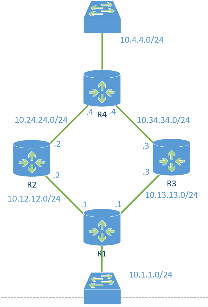
- Packet Tracer
- The Election Criteria
- Criteria that must be considered
- Next Hop
- Route Specificity
- The Smaller the subnet, the more specific the route is, allowing it to take presence
- Floating Static Route
- Administrative Distance
- Lower is better
Routing protocol/Route source Default Distance Values Connected interface 0 Static route 1 Enhanced Interior Gateway Routing Protocol (EIGRP) summary route 5 External Border Gateway Protocol (eBGP) 20 Internal EIGRP 90 IGRP 100 OSPF 110 Intermediate System-to-Intermediate System (IS-IS) 115 Routing Information Protocol (RIP) 120 Exterior Gateway Protocol (EGP) 140 On Demand Routing (ODR) 160 External EIGRP 170 Internal BGP 200 Unknown 255 - Metric
- Hop Count - Lower is Better
- Criteria that must be considered
Revisiting the Routing Protocols
- Distance Vector vs Link State
- DV
- Protocols
- RIP - Internal
- BGP - External
- EIGRP - Internal
- Only Knows What the neighbor tells it
- Memory/Processor Efficient
- Loop Prevention Mechanisms needed
- Protocols
- LS
- Protocols
- OSPF
- IS-IS
- Maintains a map of the network system
- Resource Consuming
- Maintains Loop free by nature
- Protocols
- DV
- Routing Protocol Flavors
- Split Horizon: Stopping Loops, Stopping Continuity
- I will not send out an update on an interface I received the information on
- This causes issues in the some cases
- Solutions
- Disable Split Horizon
- Use sub-interfaces - Preferred Option
- For Reference
- Triggered Updates
- Maximum Metric
- Route Poisoning
OSPF
OSPF Protocol Overview
- OSPF Overview
- Standards-Based, Link State Interior Gateway Routing Protocol (Maintains LSDB)
- Designed for IPv4 (OSPFv2) and IPv6 (OSPFv3)
- Uses the Dijkstra SPF Algorithm
- Works for simple (single area) Networks and Advanced (Multi Area)
- Single Area - CCNA
- Multi Area - CCNP/IE
- Doesn’t use UDP or TCP - Stands Alone
- How OSPF works (Much Better than RIP)
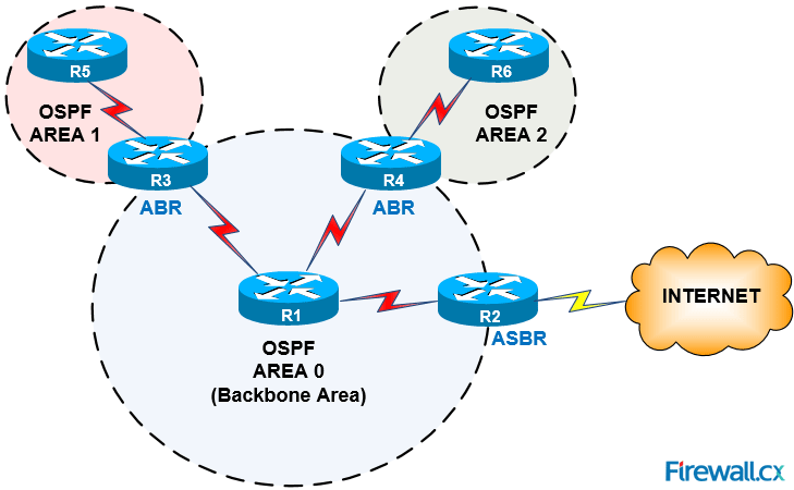
- OSPF Area Design and Terms
- All Areas must connect to area 0
- All Routers in an area have the same topology table
- Goal: Localize Updates within an area
- Requires a Hierarchical Design
- Summarization
- Autonomous System Boundary Router (ASBR)
- Partnering Company
- ISP
- OSPF Area Design and Terms
Neighbor Relationships
- Phases of OSPF Neighbor Relationships
- Packets: Hello, DBD, LSR, LSU, LSA, LSACK
- LSA - Link State Advertisement
- LSACK - Link State Acknowledgement
- Understanding OSPF Neighbor Relationships
- Determine your own Router ID
- The Router ID is Simply the Router’s Name in the OSPF Process
- Highest Active Interface IP address when OSPF starts (Lookbacks beat physical interfaces)
- Can Be hard-coded using the Router-ID command
- Add Interfaces to the link state database (Dictated by the network command)
- Send A Hello Message on chosen Interfaces
- Once Every 10 seconds on broadcast/P2P Networks
- Once Every 30 seconds on NBMA Networks
- Contains all sorts of information:
- Router ID
- Neighbors*
- Hello and Dead timers*
- Router Priority
- Network Mask*
- DR/BDR IP Addresses
- Area ID*
- Authentication Password*
- Receive Hello
- Check Hello / Dead Interval
- Check Netmask
- Check Area ID
- Check Authentication Passwords
- Send Reply Hello
- Am I listed as a neighbor in your hello packet?
- (if yes, reset dead timer)
- (if no, add as new neighbor)
- Am I listed as a neighbor in your hello packet?
- Master - Slave Relationship Determined
- Determined by “Priority”, Router-ID breaks tie
- Master Sends Database Description (DBD) packet
- DBD = Cliff Notes of link-state database
- Slave sends its DBD packet
- DBDs are acknowledged and reviewed
- Slave requests details (Link State Request - LSR)
- Master sends updates (Link State Updates - LSU)
- Master requests details (LSR)
- Slave sends updates (LSU)
- Neighbors are synchronized!
- Full State
- Now it’s time to run the Dijkstra SPF algorithm to figure out what to do with all this data
- Determine your own Router ID
The Roll of the DR and BDR
- Understanding how OSPF processes updates
- Understanding the full relationship fireworks show
- How the DR and BDR remedy the issue
- DR Frequency 224.0.0.6
- BDR will take over if DR dies at the same frequency
- They send out the updated on 224.0.0.5 which is all OSPF Routers
- OSPF default priority 1
- If not changed, highest router ID will be elected
ip OSPF priority- used to set an interface priority- priority 0 will caused the interface to never be chosen as the DR/BDR
- Designated Router should be a hub, not a spoke connection
- Priotoity is set on a per-interface basis
- Point-2-Point Links
- There is no need for a Designated router on a point to point link since its P2P
- DR is only needed on a multi-access segment
- Does the priority matter?
- Maybe: depends on the type of network segment
- Cloud based network segments, it does matter where the DR and BDR are located.
- Maybe: depends on the type of network segment
- The Full Neighbor relationships only form between the connections to the DR and BDR devices
- 2-way connections are formed between everything else, Friend-Zoned
OSPF Lab
OSPF Base Configuration
- OSPF Network Configuration and verification
- Gloss: DR Election, Timer Configuration, metric adjustment, passive networks
- Configuration Focus
- Configure all routers shown to operate in the backbone area. Hardcode Router IDs so they do not easily change
- Cisco Recommends being specific as possible
- Shoe Config Command -
network 10.1.3.1 0.0.0.0 area 0 - sh ip protocols
- sh ip ospf neighbor
- debug ip ospf adj - allows you to watch the events form
- path
- Two-way
- ExStart
- Exchange
- LS Req (LSR)
- LS Upd (LSU)
- LSA
- Loading
- Full
- Determine which router became the DR; elect “Tie” as the DR moving forward
- DR Election
- sh ip OSPF interface
- Point-to-point - No designated DR
- Broadcast _ Designated DR must be elected
- Default Priority = 1, leaving them to use the higher router-id
- The Higher the priority the better chance that router will be the DR
clear ip ospf process- use to reset the DR/BDR/DOTHER- Important for a Hub and Spoke network, especially for NBMA networks
- Use
Priority 0to insure that if the DR goes down, that someone doesn’t take his place
- DR Election
- Adjust the metric of OSPF to function well with speeds up to 10G links
- OSPF uses Cost as Metric
- Cost = 100/BW
- BW = BandWidth in mbps
- Cost = 100/BW
- Under an interface you can assign the cost
- ip ospf cost
auto-cost reference-bandwidth 10000
- OSPF uses Cost as Metric
- Ensure “Shoe” does not form OSPF neighbors on its LAN network.
passive-interface _/_passive-interface default- Cisco Preferred Methodno passive-interface _/_
- Adjust the Hello timer on “Sock” WAN interface to send Hello message 1/sec
- Go onto the interface you want to change
ip ospf hello-interval _
- Go onto the interface you want to change
- Bonus: Create loopback interfaces in such a way that Router IDs are pingable from any router
- To do this you must create the loopback interface, and then assign the network for the OSPF network
int loopback 0ip address 4.4.4.4 255.255.255.255network 4.4.4.4 0.0.0.0 area 0
- Configure all routers shown to operate in the backbone area. Hardcode Router IDs so they do not easily change
Troubleshooting Core OSPF
- The Networks done gone off and blown up!
- Configuration Focus
- A Junior network administrator took care of things while you were on vacation and now the entire network is down.
- Troubleshoot the network such that all connectivity is restored and all routers are forming expected OSPF neighbor relationships.
- Duplicate Router IDs will cause a complete network outage
- Troubleshooting steps
- sh ip protocol
- sh ip route
- sh ip ospf neighbor
- sh ip ospf int
- sh run
- clear ip ospf process
- sh ip int brief
- debug ip ospf adj
- debug ip ospf packets
u all- Stops all debugs- Google! - you can find what each package are
- hello-timer
- sh run interface /
- sh run int /
- serial encapsulation
- HDLC - Default Encapsulation
- PPP - Industry Standard
- serial encapsulation
- Mismatched area ID
- sh run | sec OSPF
- Troubleshooting steps
- Duplicate Router IDs will cause a complete network outage
- Configuration Focus
Understanding Multiarea
- Why we do multiarea designs in OSPF
- All Routers in an Area must have the same link state database
- Every Route, Every Change must be known
- The Larger the network, the more unruly the database becomes
- Area boundaries allow you to summarize
- Reviewing the Terms and Roles
- Summarization - Summarizes the network routing table
- ABR - Area Border Router
- ASBR - Autonomous System Boundary Router
- Connects OSPF to and Outside Network
- Design Constraints
- All areas must connect to area 0
- All Routers in an Area have the same topology table
- Goal: Localize Updates within an Area
- Requires a Hierarchical Design
- Virtual Link - The Band-Aid
MultiArea OSPF Lab
- Implement a Multiarea OSPF Network
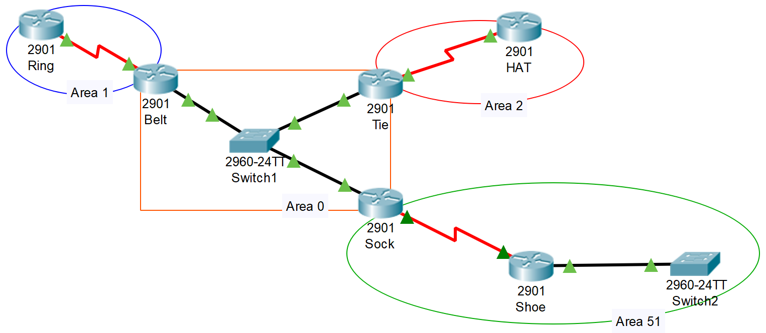
- Configure all routers shown to operate in a multiarea configuration. Tie, Belt, and Sock will act as ABRs.
- Add five (5) loopback interfaces to ring, Hat, and Shoe. They should be contiguous to existing area subnets.
- Add an Efficient summary route to area 1, 2, and 51. Verify impact on the routing table of other routers.
- Add a lookback interface to Belt with the IP address 184.51.1.1. This will simulate and Internet connection
- Have Belt Advertise the default route to the other routers via OSPF. The route should exist even if Belt does not have the default route.
- OSPF MultiArea Network Packet Tracer
EIGRP
EIGRP Protocol Overview
- OSPF vs EIGRP
- OSPF
- Link State Protocol
- Maintains and shares the full routing table
- Large Overhead
- SPF - Shortest Path First Algorithm
- EIGRP
- Advanced Distance Vector Protocol
- Shares Partial pieces of the routing table
- Backup Routes instead of Routing Database
- Dual - Defused Update Algorithm
- Topology Table instead of Link State table
- Why you would choose to Use EIGRP
- Backup Routes (Fast Convergence / Dual)
- Simple Configuration
- Flexibility in Summarization
- Unequal Cost Load-Balancing
- Combines Best of Distance Vector and Link State (Limited Routing Information, but backup paths)
- OSPF
- The Unique Terms of EIGRP
- EIGRP Tables and Terminology
- A Router Running EIGRP maintains Three Tables:
- Neighbor Table
- Topology Table
- Closest think to Link State Database
- Successor
- Feasible Successor
- Routing Table
- Best of the Best Routes
- LoadBalancing Equal and Unequal
- Feasible Distance (FD)
- How Far it is from your router to get to a network
- Advertised Distance (AD)
- How far it is from the router who told you about this route
- Successor
- Primary in Topology Table
- Makes it to the Routing Table
- Feasible Successor
- Secondary in Topology Table
- Not in Routing Table unless it is promoted to Successor in the event of an outage.
- Active Route
- Router is trying to find a backup
- Sending out Query Messages
- Passive Route
- Everything is A-Okay.
- This is what you want
- A Router Running EIGRP maintains Three Tables:
- EIGRP Tables and Terminology
- The Rule of Feasible Successor-ness
- To Be Considered a feasible successor, the AD must be less than the FD of the Successor
- Loop Prevention Mechanism
- To Be Considered a feasible successor, the AD must be less than the FD of the Successor
Neighbors and Metric
- The Neighbor Language of EIGRP
- Visiting the Friendly EIGRP Neighborhood
- Hello: Forms Relationship
- Update: Sends Updates
- Query: Asks about Routes
- Reply: Response to a Query
- Ack: Acknowledges the update, query, and reply messages
- Visiting the Friendly EIGRP Neighborhood
- Becoming and EIGRP K-Value Nerd
- Understanding EIGRP Metric Calculation
- Bandwidth (K1)
- Static
- Delay (K3)
- Static
- Reliability (K4 and K5)
- Dynamic
- Loading (K2)
- Dynamic
- MTU
- Formulas
- $Metric = \left [K1BW + \frac{K2BW}{256-load} +K3*delay \right]* \frac{K5}{reliability + K4}$
- $$BW = {\dfrac{10^7}{BW}}$$
- Delay=Delay in microseconds
- $$Real (Default) Metric = 256*(Slowest BW+All Link Delays)$$
- $$BW = {\dfrac{10^7}{BW}}$$
- Delay=Delay in microseconds
- $Metric = \left [K1BW + \frac{K2BW}{256-load} +K3*delay \right]* \frac{K5}{reliability + K4}$
- Bandwidth (K1)
- Understanding EIGRP Metric Calculation
EIGRP Lab
EIGRP Base Configuration
- Diving into EIGRP Configuration
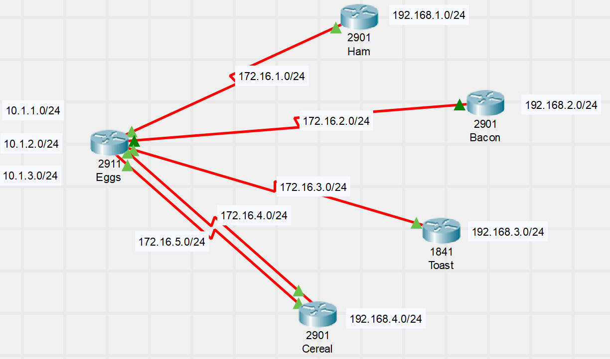
- Configure EIGRP Routing on all Routers in the autonomous system 90. Use network-specific wildcard masks at the lead office.
- Verify the impact of auto-summarization, then disable it.
- Introduce a manual summary route at the lead office. The more specific the route, the better tasting your eggs.
- Add a secondary connection to the Cereal router and verify equal cost load balancing is working.
- Modify the bandwidth on the secondary line to 1 Mbps. Adjust EIGRP to enable unequal cost load balancing.
- Modify the hello/hold timers to Cereal so failover occurs in less than 5 seconds.
- EIGRP Base Configuration Packet Tracer
IPv6 Routing
- IPv6 Addressing and Shortening
- Address size moved from 32-bit (IPv4) to 128-Bit (IPv6)
- Provides 340,282,366,920,938,463,463,374,607,431,770,000,000 …Addresses
- To make addresses more manageable, divided into 8 groups of 4 hex characters
- 2001:0050:0000:0000:0000:0AB4:1e2B:98AA
Rule 1:Eliminate groups of consecutive zeros- 2001:0050::0AB4:1e2B:98AA
Rule 2:Drop leading zero- 2001:50::AB4:1e2B:98AA
- Subnetting IPv6
- Most common Subnet /64
- EUI-64 Which uses the device Mac Address for the last half of the IP address
- Global Addresses
- Have their High-level 3 bit set to 001 (2000::/3)
- Global Routing prefix is 48 bits or less
- Subnet ID is comprised of bits are left over after Global routing prefix
- The Primary addresses comprising the IPv6 internet are from 2001::/16
- /32 Subnets assigned to Providers
- Provider Assigned
- /48, /56, /64 Subnets assigned to Customers
- /32 Subnets assigned to Providers
- Most common Subnet /64
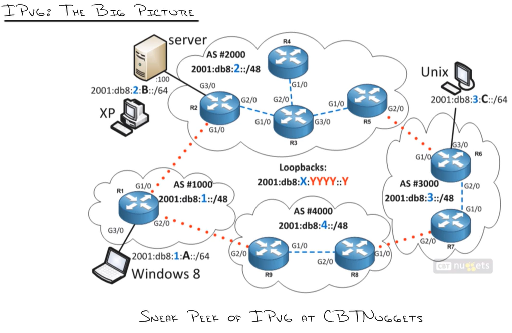
- The IPv6 Network Big Picture
IPv6 Routing Lab
Configuring OSPFv3 Routing
- Handling IPv6 Routing with OSPF
- Prompt:
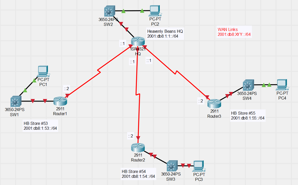
- Heavenly Beans is a wildly successful coffee house chain that promises ‘a little piece of heave’ with each cup of coffee. The IT department has chosen to use IPv6 addressing for all new regions moving forward. The most recent expansion to South Carolina will be the IPv6 pilot. Accomplish the following objectives:
- Perform IPv6 addressing of the shown network. Note: X = HQ Office Number, YY = Store Number
- Configure OSPFv3 to fully route the shown network
- Verify routing is functioning correctly with appropriate show commands and ping-based testing.
- Heavenly Beans is a wildly successful coffee house chain that promises ‘a little piece of heave’ with each cup of coffee. The IT department has chosen to use IPv6 addressing for all new regions moving forward. The most recent expansion to South Carolina will be the IPv6 pilot. Accomplish the following objectives:
- OSPFv3 Packet Tracer
Configuring EIGRP for IPv6
- Configure EIGRP for IPv6 Routing for the Heavenly Beans Network
- Prompt:
- Heavenly Beans has decided to move away from OSPFv3 in favor of EIGRP for IPv6.
- Remove the OSPFv3 configuration from all routing devices.
- Configure EIGRP for IPv6 to fully route the shown network.
- Verify routing is functioning correctly with appropriate show commands and ping-based testing.
- Heavenly Beans has decided to move away from OSPFv3 in favor of EIGRP for IPv6.
- IPv6 EIGRP Packet Tracer
WAN Technologies
Understanding Point-to-point connections
- Leased Line Lingo - Learning the terms
- WAN Links define a new type of L1 and L2 connectivity
- Allows Links to the Internet or other offices
- Many different types and prices
- Physical - Serial Physical Connections
- Data Link - Frame Relay, ATM, PPP, HDLC…
- Point to Point Terminology
- WAN Link - Connects your building to something that is far away
- Point-To-Point Link - Connection from location, directly to another location
- Usually Serial
- Leased Line / Circuit / Link
- CAS connection
- Serial Line
- Kind of connection we have
- T1 / E1 Line
- Measure of Speed
- T1 - 1.544m
- E1 - 2.048m
- Measure of Speed
- Point of Presence (POP)
- Where the service provider is present.
- How these Connections look “for real”
- DEMARC
- CSU/DSU
- DB-60
- V.35
- Smart Serial
- WIC - Wan Interface Device
- T1 or E1 with CSU/DSU
- the DSO Building Blocks
- T1 and E1 Leased Lines (Technically CAS and CCS) Build w/multiple DS0 Channels
- DS0 = 64Kbps, the amount required for voice
- T-Series
- T1 = 24 DS0 (1.544 Mbps)
- T3 = 672 DS0 (44.736 Mbps)
- E-Series
- E1 = 32 DS0 (2.048 Mbps)
- E3 = 512 DS0 (34.368 Mbps)
Getting the Layer 2
- What? No MAC Address?
- Frame Relay and ATM
- Can run over Serial Connections
- NBMA - Non Broadcast MultiAccess connection types
- Uses PVC - Permeant Virtual Circuits
- Frame Relay and ATM
- The two Point-to-Point choices
- HDLC…Nothing there to unpack
- HighLevel DataLink Control
- Industry standard Layer 2 communication protocol allowing any vendor to connect to any other vendor router simply with no configuration
- Cisco stepped in to make it proprietary
- PPP…Four Major Categories of Features
- Point-to-Point connection
- Allows to you to connect any vender router to another over a wan link
- Industry Standard
- HDLC…Nothing there to unpack
- PPP architecture and features
- Compression
- Trades the CPU for faster bandwidth
- Not widely used anymore
- Callback
- Connect in on a router, get disconnected, and the router would call them back
- Not widely used anymore
- MultiLink
- Combine multiple WAN connections into 1 connection
- CPU Heavy
- Authentication
- Ensures the other other router is who they say they are.
- PAP
- Password Authentication Protocol
- Cleartext
- Two-way Authentication
- CHAP
- Challenge, Handshake, Authentication Protocol
- Encrypted
- Preferred Standard
- Compression
WAN Technologies LAB
Configuring a Point-to-Point WAN Connections
- HDLC / PPP Live Lab
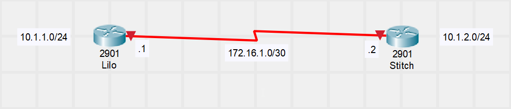
- CConfigure the following network in its entirety using HDLC encapsulation for the 64Kbps WAN link. Use static routing to provision full Lilo-to-Stitch office connectivity.
- Convert the link to PPP encapsulation.
- Configure PPP PAP authentication between Lilo and Stitch. Use the appropriate debug commands to prove authentication is occurring.
- Convert to using PPP CHAP authentication.
- Add a second WAN link between Lilo and Stitch, also running at 64Kbps. Engage PPP Multilink to double the bandwidth between the two locations.
- HDLC / PPP Live Lab
The WAN Evolution
- Moving from leased lines to scalability
- Leased Lines (circuit Switched Technology)
- Inflexible
- Unused bandwidth
- Expensive
- Packet Switched (PVC)
- Virtual Circuit
- Each Packet is ‘Destinationed’
- Not-as-expensive
- Leased Lines (circuit Switched Technology)
- Understanding packet switched networks
- X.25 (1976), Frame Relay, ATM, MPLS
- Virtual Circuits defined (PVC), Committed information rate (CIR) for each
- Unique Layer 2 address needed (Fills the MAC role)
- The Future: MPLS, METROE, VPN
- Metro Ethernet - Fiber gone wild
- There a lot of Dark Fiber
- Transatlantic Fiber
- Multiprotocol Label Switching (MPLS)
- Moves them up from the physical layer to the data link layer
- Abstraction of the network layer
- Virtual Private Networks (VPN)…of the IPSEC type
- Metro Ethernet - Fiber gone wild
Internet Technology
Cable and DSL
- Understanding the technology fundamentals
- Internet Connection Options
- ISPs must connect to each other and to customers
- DSL and Cable were originally treated at home environments
- Copper cabling, repurposing spectrums
- Distance from the Central Office (CO) dictates Maximum Speeds
- Mostly asymmetric Connections
- One rate is more than another
- Internet Connection Options
- The PPPoE Puzzle
- The Place of PPPoE
- DSL and Cable use a “Local Loop” Connections
- PPPoE adds authentication mechanisms to it
- Typically used by DSL, Passthrough or direct
- The Place of PPPoE
Internet Technology Lab: PPPoE Configuration
- Configuring a PPPoE client connection
- Configure the Neo router fa0/0 to connect to the ISP with a PPPoE DSL connection
- The Neo router should learn its public address dynamically
- User the Hostname “CBTNuggets” with a password of “IsQuiteFun” to authenticate
- Configure a default route out the Dialer interface you create on your router
- Use the proper show commands to verify the PPPoE connection is working
- Ping 4.2.2.2 or 8.8.8.8 to test internet connectivity
- Configure the Neo router fa0/0 to connect to the ISP with a PPPoE DSL connection
VPN Solutions
- Four Key VPN Objectives
- Confidentiality - Stopping prying eyes
- Authentication - Validate the identity
- Data Integrity - Preventing Change
- Anti-Replay - Eliminate Deja-vu
- Understanding VPN Options
- Site-to-Site
- Client (Remote Access - IPSec)
- Administrative Burden that comes with Device management and client management
- SSLVPN
- DMVPN
- Dynamic Multipoint VPN
- The Whole Point of GRE
- IPSec is Limited to IP-Based protocols and only unicast traffic
- RFC Generic Routing Encapsulation (GRE) Fixes that
- GRE by itself is unsecure; needs IPsec if used publicly
- DMVPN relies heavily on multipoint GRE tunnels
Internet Technology Lab: GRE Tunnel Implementation
- GRE Configuration Live Lab
- Fish store 29 needs to get connected to the Corporate office. The new Fifi’s Flopping Fish CIO is convinced that network security is a scam and would like to deploy unencrypted tunnel between Store 29 and the corporate offices. You must set up this tunnel and ensure routing is fully functional between the locations.
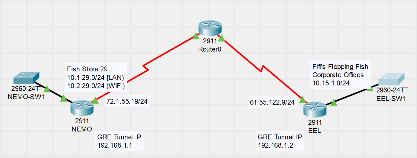
- Implement a GRE tunnel between the Nemo and Eel routers using 192.168.1.0/24 subnet for internal IP addressing.
- Configure OSPF routing between the two offices. OSPF should advertise the LAN and WIFI networks at store 29 to the corporate office; however, it should not send Hello messages out the LAN interfaces, OSPF communication should only occur within the GRE tunnel.
- Verify you have achieved the objectives by confirming OSPF neighbor relationships and routing tables.
- Fish store 29 needs to get connected to the Corporate office. The new Fifi’s Flopping Fish CIO is convinced that network security is a scam and would like to deploy unencrypted tunnel between Store 29 and the corporate offices. You must set up this tunnel and ensure routing is fully functional between the locations.
- GRE Tunnel Lab Packet Tracer
CCNA Welcomes BGP
- A Practical Description of BGP
- The Internet
- The ARPinet before the “Cloud”
- The Cloud of Clouds
- Clouds are autonomous systems.
- EGP (Exterior Gateway Protocol)
- BGP Only
- Untrusting
- Slow
- Penalty Box
- IGP (Interior Gateway Protocols)
- All other protocols
- Trustful
- Fast
- Builds Neighbors Quickly
- MPLS
- Allows you to make it feel as if you own the network.
- Some support
- OSPF
- EIGRP
- Opens them up to attack
- They form a BGP relationship instead
- The Internet
- When should you NOT run BGP
- You Don’t have “Beefy” Routers
- You’re only connected to ONE External AS (ISP)
- You don’t have enough bandwidth to receive updates
- You don’t fully understand BGP
- When should run BGP
- You need High-Availability through multiple ISPs
- You are a service Provider
- Large Networks with “DEMARC” points to other Divisions, Partners, or Service Providers
- The BGP resume
- Reliable Updates (TCP-Based, Port 179)
- Batch Updates only (5 Seconds Internal, 30 seconds External)
- iBGP
- eBGP
- Complicated “Metric” for finding the best route
- All neighbors are manually set up
- Complex filters are typically used
- The routing Protocol of the Internet
- Management of Trust and Untrust
- Routing through autonomous systems instead of routers
- The slowest routing protocol in the world
- Primarily Service Provider, but also Enterprise Customer
Internet Technology Lab: Basic BGP Configuration
- Configuring a BGP Neighbor and Advertise routes
- The MAX Corporation has decided to bring up redundant connectivity for their corporate office to ensure their email and web hosting services are resilient should the connection to their primary ISP fail. They would like to test BGP with their primary ISP before entering into a long term agreement with the secondary provider.
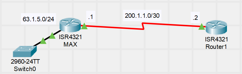
- Configure BGP for the MAX organization in AS 5000.
- Establish a neighbor relationship between the MAX and ISP routers. The ISP is running in AS 2500. Confirm the MAX router is receiving BGP routers from the ISP.
- Advertise the 63.1.5.0/24 network owned by MAX via BGP to the ISP router. Advertise a summary route to 63.2.0.0/16 to the ISP (class B address MAX acquired after a hostile take over of the MIN organization).
- Configure the ISP to advertise a default router to MAX.
- BGP Lab Packet Tracer
- The MAX Corporation has decided to bring up redundant connectivity for their corporate office to ensure their email and web hosting services are resilient should the connection to their primary ISP fail. They would like to test BGP with their primary ISP before entering into a long term agreement with the secondary provider.
Infrastructure Services
Understanding HSRP
- Two is one, one is none
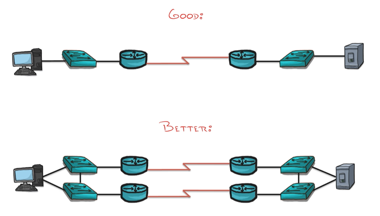
- Redundancy is key
- Better
- This is the bet of the best scenarios.
- Hardware Redundancy
- Route Redundancy
- FHRP Options
- First Hop Redundancy Protocol
- Creates a virtual .1 IP address
- Hello messages are sent every 3 seconds
- HSRP
- Creates a shared virtual Mac address as well
- GARP
- Gratuitous Arp
- Understanding and Comparing the FHRP Players
- Common Ground:
- Redundancy Focus
- Virtual IP and MAC
- Keep
- HSRP Unique Features
- V1: 0000.0c07.ac–
- Seconds
- 256 HSRP Groups
- Group = Set of 2 or more devices
- V2: 0000.0c9f.f—
- msec
- 4096 HSRP groups
- Created in 1994
- Works for Routers and Layer 3 switches
- V1 and V2 are not compatible
- V1: 0000.0c07.ac–
- VRRP and GLBP unique features
- Virtual Router Redundancy Protocol
- Created in 1999
- Multi Vender Eco system
- Default hello timers
- 1 second dead after 3
- Assign the 1 IP address to multiple devices
- Gateway Load Balancing Protocol
- Released in 2005
- Cisco Proprietary
- Creates two virtual mac address and shares them between the two devices
- Virtual Router Redundancy Protocol
- Common Ground:
- Key HSRP concepts
Infrastructure Services Lab: Configuring HSRP
- Configuring and testing HSRP Failover
- Squid Shack implements Point of Sale (POS) terminals in each of their stores. If these terminals are unable to reach their parent server at Squid Shack Corporate offices, squid sales cannot be processed potentially causing an untimely end of hundreds of squid. Ensure the routers at each location are configured for failover for the most redundant of possible configuration.
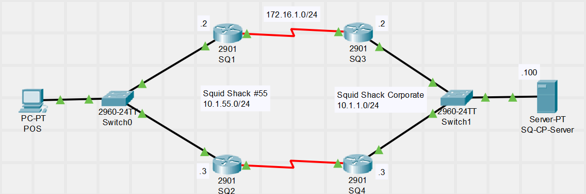
- Verify configuration. Ensure Squid Shack store / Corporate routers have correct routing information/
- Configure HSRPv2 at both locations where SQ1 and SQ# are the primary routers. User the .1 IP address as the virtual IP.
- Configure HSRP so SQ1 and SQ3 regain primary router status should failover occur.
- Verify HSRP is working correctly using show commands. Perform a live failover test to reassure Squid Shack of the network stability.
- HSRP Lab Packet Tracer
- Squid Shack implements Point of Sale (POS) terminals in each of their stores. If these terminals are unable to reach their parent server at Squid Shack Corporate offices, squid sales cannot be processed potentially causing an untimely end of hundreds of squid. Ensure the routers at each location are configured for failover for the most redundant of possible configuration.
Understanding the QoS Dilemma
- A type of life insurance ( or life protection )
- Not all traffic is created equal
- The ability to Dictate traffic treatment
- Prioritization
- Shaping / Policing
- Advanced Strategies ( WRED )
- Strategies to Fight the enemy
- Delay
- Jitter
- “Delay Variation”
- Packet Loss
QoS Tools
- What’s My Target
- Auto Requirements
- Jitter: < 30 ms
- Delay: < 150 ms
- Loss: < 1%
- QoS: DSCP EF
- Marking
- Bandwidth: Little
- Video Requirements
- Jitter: < 30 ms
- Delay: < 150 ms
- Loss: < 1%
- QoS: DSCP AF41
- Marking
- Bandwidth: Lots
- Data Traffic:
- Mission Critical
- Transactional
- Best Effort
- Scavenger
- Auto Requirements
- QoS Tools
- Methods Available
- Classification and Marking
- NBAR - Deep Inspection
- ToS -Type of Service
- CoS - Class of Service
- NBAR - Deep Inspection
- Queuing ( Congestion Management )
- Congestion Avoidance
- Shaping and Policing
- sHAPING Smoothing out the traffic you want
- Policing - Cuts it off the traffic you don’t want
- Classification and Marking
- Understanding Trust Boundary
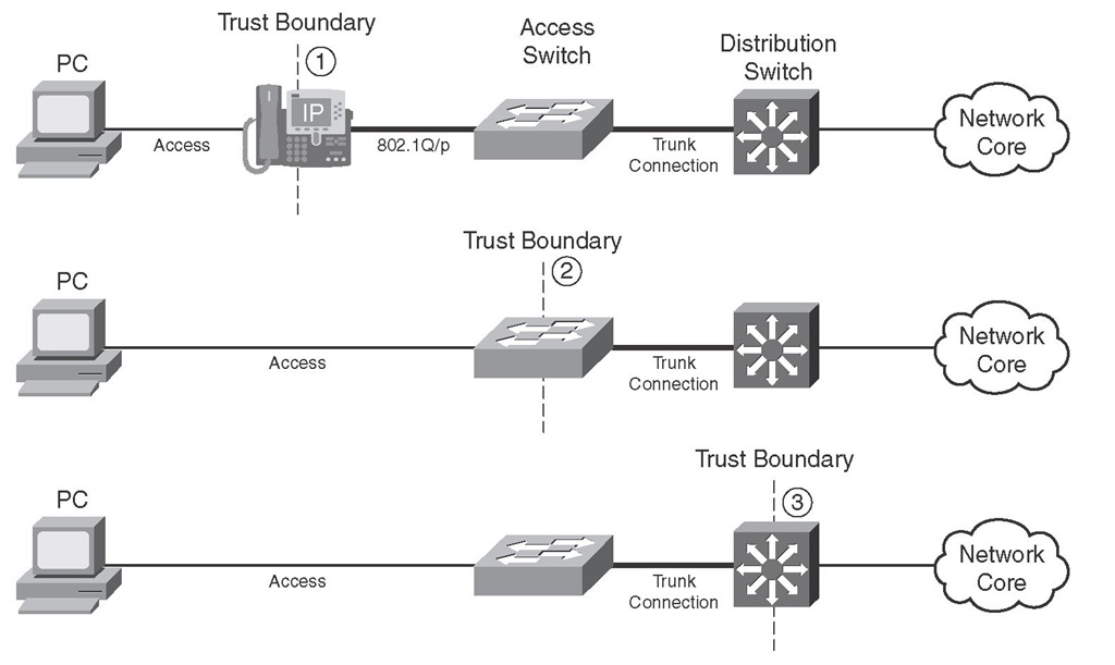 1. Best
* Ability to mark its own traffic if it’s a Cisco Phone
* Uses CDP to detect the device type
* Can mark the phone traffic
* Can mark the user traffic as well
2. Better
* Adds more hands
3. Good
* Puts a lot of strain on your router
1. Best
* Ability to mark its own traffic if it’s a Cisco Phone
* Uses CDP to detect the device type
* Can mark the phone traffic
* Can mark the user traffic as well
2. Better
* Adds more hands
3. Good
* Puts a lot of strain on your router
- Methods Available
- Queuing Strategies
- Weighted Fair Queuing (WFQ) - Low traffic senders get priority over high traffic senders
- Class Based WFQ - Divides bandwidth among classes that you define
- Used for Data traffic
- Low Latency Queuing (LLQ) - Combo of CB-WFQ, but adds a strict priority element
- VoIP
- Trust Boundary
RADIUS and TACACS+
- AAA is not just for flat tires
- What is AAA? What Can It control?
- Authentication - Validates WHO you are
- SSH
- VPN Access
- PPP Links
- AUX Access
- Console Access
- Telnet
- Dialup Modems
- Authorization - Tells what you can DO
- Multiple Privilege Modes
- Accounting - Tracks what you DID
- Authentication - Validates WHO you are
- The Authentication Street Fighters: Radius and Tacacs+
- Tacacs+
- Cisco Proprietary
- Command-by-command authorization
- Cisco ACS Server
- Packet fully encrypted
- Normally used for Network Devices
- Radius
- Industry Standard ( RFC 2865 )
- Only Password Encrypted
- Normally used for user auth
- Tacacs+
- What is AAA? What Can It control?
- Understanding the place of Radius and Tacacs
Infrastructure Services Lab: Configuring Extended ACLs
- Hone your Extended ACL skills through three exercises
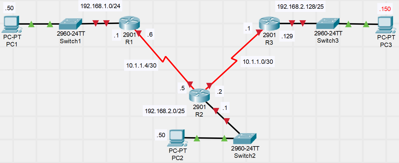
- Scenario 1: Block 192.168.2.0/25 from reaching 192.168.1.0/24 using an Extended ACL.
- Scenario 2: Block Telnet and SSH traffic originating from 192.168.1.0/24 form reaching 192.168.2.128/25 .
- Scenario 3: On R2, block all HTTP traffic coming in from the 192.168.2.128/25 offices.
- Extended ACL Lab
Monitoring Tools
Understanding IP SLA
- Understanding the purpose of IP SLA
- What IS IP SLA?
- Technically: A Contract with a service Level Guarantee
- In Cisco: A Method of Measuring Service Level by sending test traffic
- Able to Measure:
- Network Delay
- Packet Loss
- Jitter
- Voice Quality
- What IS IP SLA?
- Things you can do with IP SLA
- Other IP SLA Notes
- Measuring with IP SLA can be taken directly to a device (Server, Router, ETC…) or into an IP SLA responder
- Monitor IP SLA using SNMP/SNMP Trap Capable
- Supports QoS marking with DSCP
- Differentiate Services Code Point
- Most commonly measured metrics: Jitter and Packet Loss
- Other IP SLA Notes
Monitoring Tools Lab: Configuring IP SLA
- Implementing IP SLA Between Endpoints
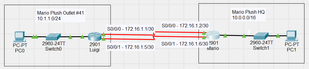
- Super Mario Plush Inc. has implemented redundant connections between the HQ and outlet stores. Mr. Mario himself has expressed his distrust in routing protocols and has directed that only static routing (yet to be implemented) between offices is resilient and adjusts the routing table based on a failed WAN connection.
- Implement IP SLA ICMP probes between the two locations for each WAN connection.
- (beyond CCNA) Configure static routing in such a way that it uses SLA results to use only valid paths for communication.
- (beyond CCNA) Test your results by disabling one of the connections and ensuring failover occurs.
- Super Mario Plush Inc. has implemented redundant connections between the HQ and outlet stores. Mr. Mario himself has expressed his distrust in routing protocols and has directed that only static routing (yet to be implemented) between offices is resilient and adjusts the routing table based on a failed WAN connection.
SNMP Concepts
- The Place and Purpose of SNMP
- The Puzzle Pieces of SNMP
- Process Overview
- Monitored Deceives
- SNMP V1, V2c, V3
- MIB / OIDs
- Monitoring Server
- Output
- IT Admin
- Version Differences
- Community Strings (RO/RW)
- Process Overview
- The Puzzle Pieces of SNMP
- SNMP Versions
- SNMP V1
- Allowed for community String monitoring of device.
- SNMP V2C
- Expanded upon SNMP V1 and allowed for 32 bit and 64 bit monitoring for faster speeds.
- SNMP V3
- Allowed for Encrypted commination with the monitoring server.
- SNMP V1
Monitoring Services Lab: SNMP Configuration
- Setting up a monitored network environment
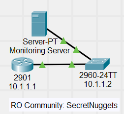
- You are a consultant for iT LLC (Making IT Cool Again). You have to implement a small office network with a router and switch and must now implement SNMP monitoring. Due to size, the PRTG 100 Free platform will suffice. Accomplish the following:
- Implement SNMPv2 monitoring for the Cisco Switch. Add the following sensors: Ping, CPU, Free Memory, Uptime, and Bandwidth monitoring for all active interfaces.
- Implement SNMPv3 monitoring for the Cisco Router. Use Auto Discovery to add common monitoring elements.
- You are a consultant for iT LLC (Making IT Cool Again). You have to implement a small office network with a router and switch and must now implement SNMP monitoring. Due to size, the PRTG 100 Free platform will suffice. Accomplish the following:
Monitoring Services Lab: Understanding and Configuring SPAN
- Understanding the place of SPAN
- Local SPAN: Selectively “Port” Traffic from select interfaces
- Combine with Wireshark wizardry for advanced troubleshooting
- Configuring SPAN on a Cisco Device
monitor session <SPAN ID>
Defining Software Defined Networking (SDN)
- What is SDN?
- The next step beyond “Traditional Network Infrastructure”
- Each device managed and controlled by its own processes
- Limited central control
- Wireless Controller
- A New world of Network Programmability (Another name for SDN)
- Software, Central control of the network
- Adapts to an ever-changing environment
- Massive Topic (CCNA Intro)
- The next step beyond “Traditional Network Infrastructure”
- Dissecting a Network Device
- Three Planes of existence
- Data Plane
- Control Plane
- Management Plane
- Every Device has its own control/data plane
- SDN Moves the control and management planes to a centralized, software controller
- Three Planes of existence
- Northbound and Southbound Interfaces
- Not physical interfaces on a device; SDN Concept
- Southbound Interface (SBI) represents communication between controller and device
- Northbound interface (NBI) represents communication between controller and outside programs
How Cisco Does SDN
- The SDN World as we know it
- Currently an Olympic race of many runners to the perfect controller
- Duplicating efforts
- Core feature definition needed
- OpenDaylight (ODL) Now exists as a Linux Foundation Project
- Backed by many vendors
- Contains many built-in SBIs
- Cisco has adopted ODL and created Cisco Open SDN Controller (OSC)
- Currently an Olympic race of many runners to the perfect controller
- How Cisco does SDN
- “Traditional” SDN
- Cisco Open SDN Controller (OSC)
- Supported by a few Nexus Switches / Cisco ASR Router
- OpenFlow integrations / Support
- Application Centric Infrastructure (ACI)
- Data Center SDN
- Application Focus (Mostly VM)
- Uses application policy infrastructure controller (APIC)
- “Traditional” SDN
- APIC Enterprise Module (APIC-EM)
- The SDN Hybrid: APIC-EM
- Redefines SDN (Hybrid Model) by keeping control plane in devices
- Northbound interfaces still allows outside integration
- Devices controlled via telnet, ssh, SNMP
- Allows for expansion through installable apps
- Created by different Cisco groups
- Appear as integrated sections in APIC-EM
- Path Trace APP
- Path Trace ACL Analysis tool
- Redefines SDN (Hybrid Model) by keeping control plane in devices
Ryan N Gay
Electrical Engineer (Networking)
I am a lover of Linux, Apple, and all things that involve networking.